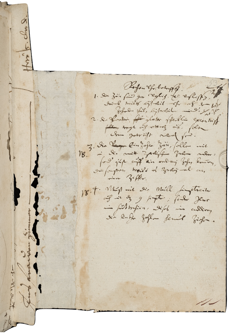
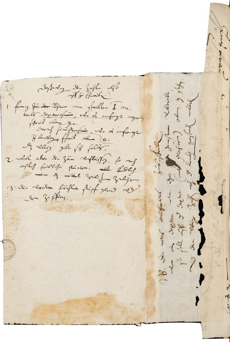
Schickard writes, in transcription:
Rechen Uhr betreffs.
1. Die zän seind gar vngleich und vnfleißig. Drumb treibts bißweil mehr als den zehenden theil, bißweilen minder. (were besser 20 zän)
2. die vordere glatte scheiblin excentrisch, tregt auch etwas aus, sollten dran geträht worden sein
3. Die einzehte zän sollen nit in die mitt zwischen zween andere: sonder just auff ain ordinarj zahn kommen, denn sonsten treibt es zweymal an einer ziffer.
(NB)4. Muß nit die null simpliciter, auch nit das 9 simpliciter, sondern jene im Subtrahieren, dieses im Addieren die linkhen zahlen herausziehen. (NB)
Deßwegen die zahlen also auffzuschreiben:
1. fang zu der Rechten am scheiblen 1 an, treibs dextrorsum, wo es anfangt angreifen schreib oben 9. Danach sinistrorsum, wo es anfangt zu bewegen, schreib oben 0, das vbrig gibt sich selbs.
2. weil aber die zän vnfleißig, so mach erstlich heimbliche puncten. Endlich nimm das mittel zwischen zweyen.
3. Die vordere löchlin stupf gerad vnder den ziffern.
NB. Die rotas Arithmeticas zu beschreiben. Wan ein dextra rota ihre sinstram vmtreibt, so soll auff der dextra (ante conversionem) oben 9 stehn vnd die vbrige zahlen nach der linkhen geschrieben werden."
or translated to English:
Where the calculating clock is concerned:
1. The teeth are uneven and unsuitable. Sometimes more than a tenth part is driven, sometimes less. 20 teeth would be better.
2. The front eccentric smooth disk drags a little, it should be turned.
3. (NB) The single tooth (note: for the carry of tens) should not be placed in the middle between two others. Should it touch right onto a numeral tooth, it will push the number forward twice.
4. (NB) Only the 0, and also the 9 should move the left number, the first when subtracting, the next when adding.
This is why the numbers must be written in this way:
1. Start on the right with disc 1, turn right, where the disc starts to engage, write 9 on top, then turn to the left, where it starts to move, write 0 on top. The rest is self-explanatory.
2. Where the teeth are unevenly spaced, first place hidden points, then take the middle between the two.
3. The front holes should be right in front of the numbers.
NB: To annotate the arithmetic wheels. When a right wheel is driving its left wheel, on the right wheel it should read 9 on top before the transfer, and the other numbers should be written to the left.
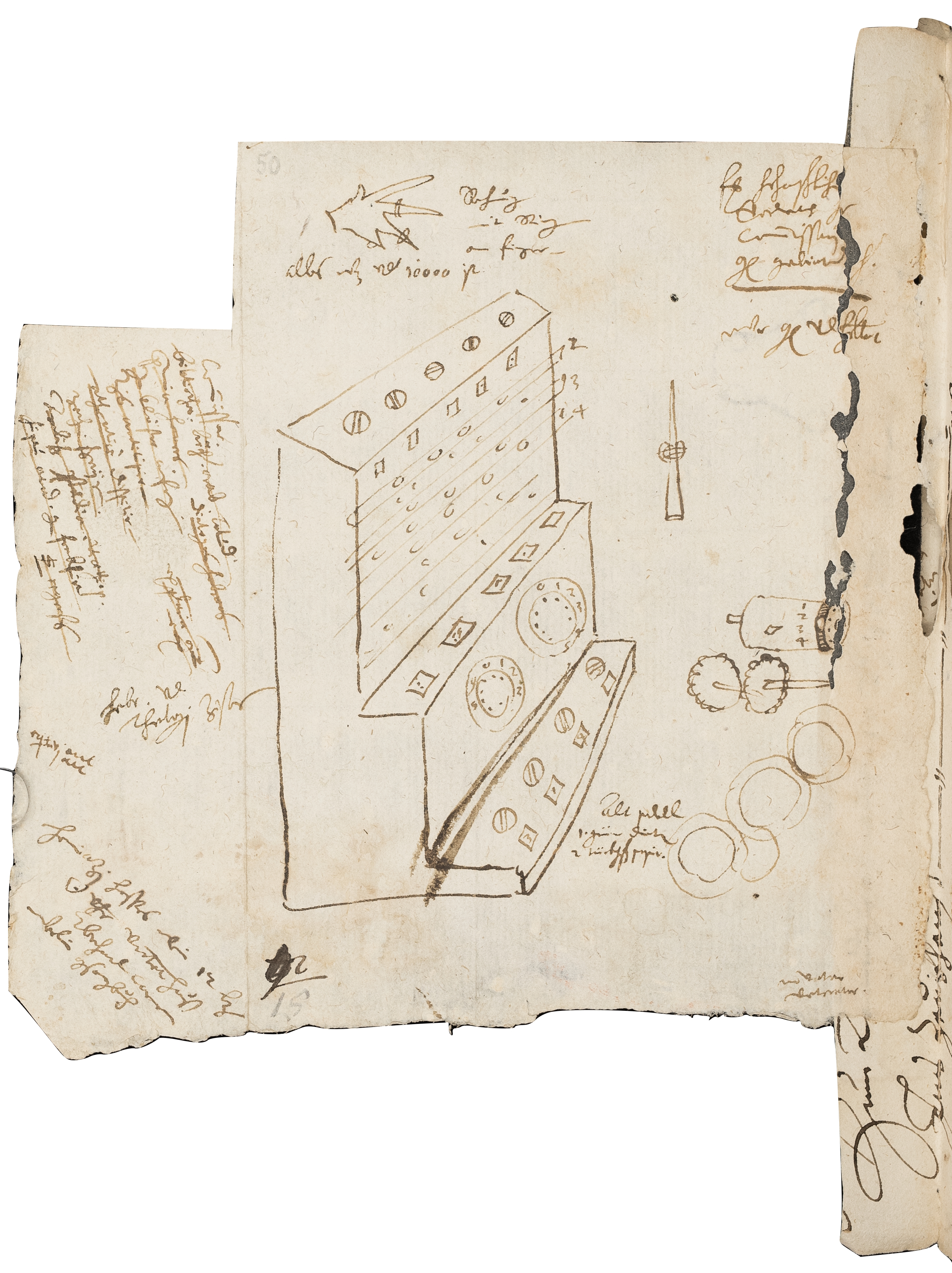
Original: Stuttgart, Württembergische Landesbibliothek, Cod. hist. 4° 203, p. 50, 53, 54
The original of Schickard's letter to Kepler of 20 September 1623 has been lost. There are however printed copies. The conversation between Schickard and Kepler takes place in Latin, as befits a pair of 17th century scientists.
He writes:
Porro quod tu logistice, idem ego mechanice nuper tentavi & machinam extruxi, undecim integris & sex mutilates rotulis constantem, quae datos numeros statim automaton computet, addat, subtrahat, multiplicet dividatque. Rideres clare, si praesens cerneres quomodo sinistros denarium vel centenarium supergressos, sua sponte coacervet aut inter subtrahendum ab eis aliquis sussuretur.
Translated:
In addition, like you logically, I have tried to do the same mechanically, and have built a machine, consisting of eleven whole and six mutilated gears, that adds, subtracts, multiplies and divides the numbers set in it automatically. You would laugh brightly if you could see here how the units are transferred automatically to the tens and hundreds, and how they are taken away when subtraction is done.
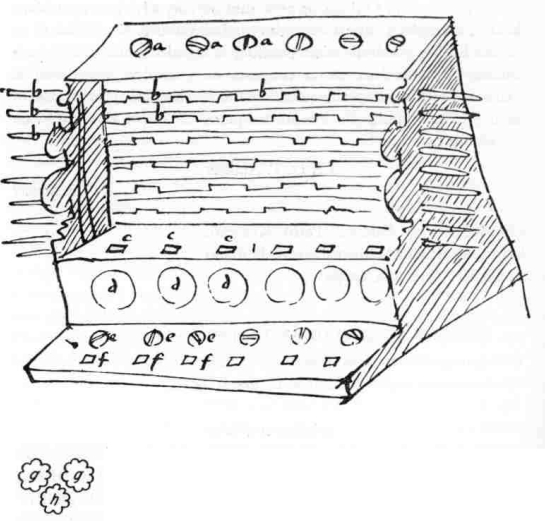
The second letter to Kepler mentioning the calculator, dated 24 February 1624, is or was in the library of the Pulkovo Observatory in St Petersburg. It is accompanied by a sketch, which is essential to understand the description.
Schickard writes:
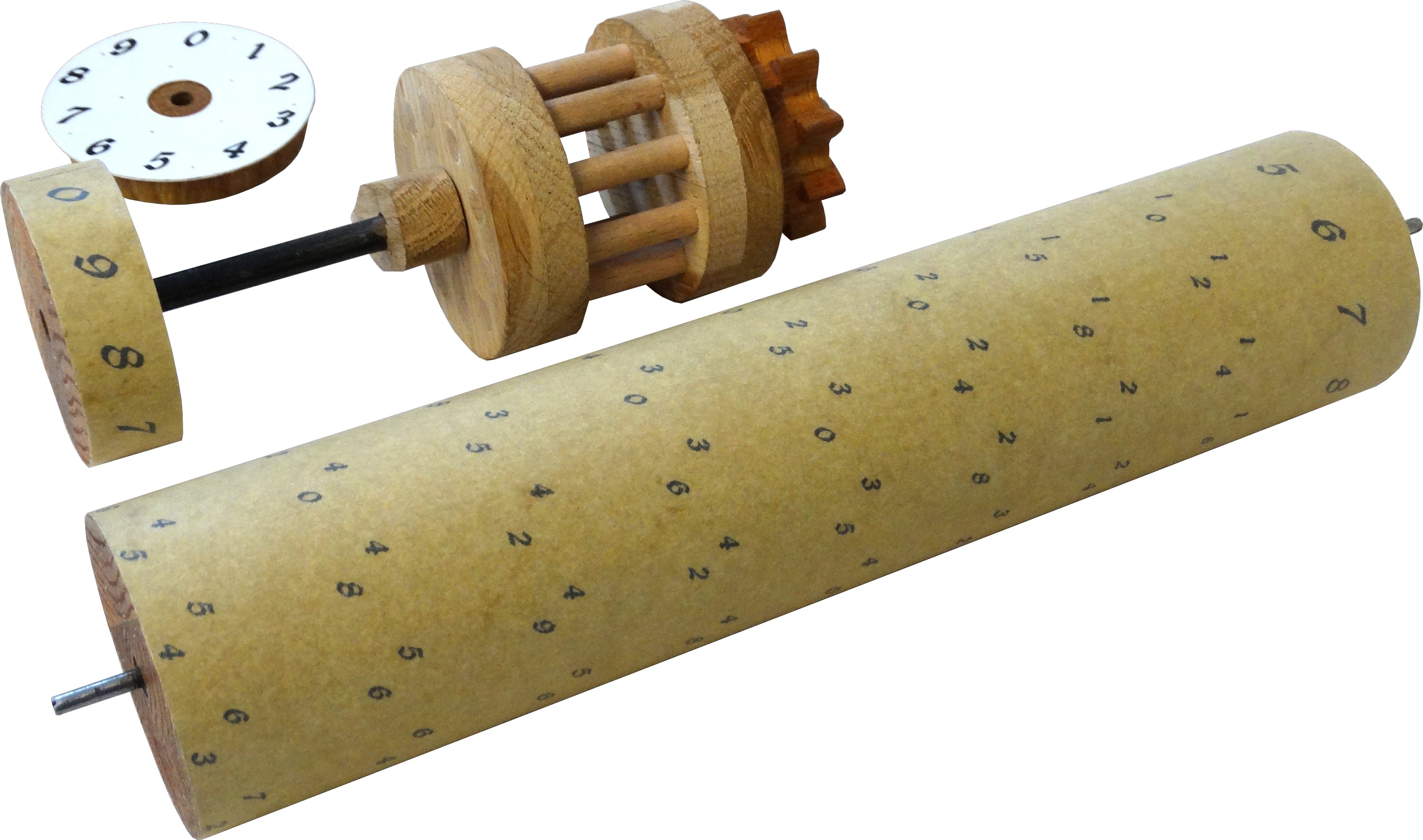
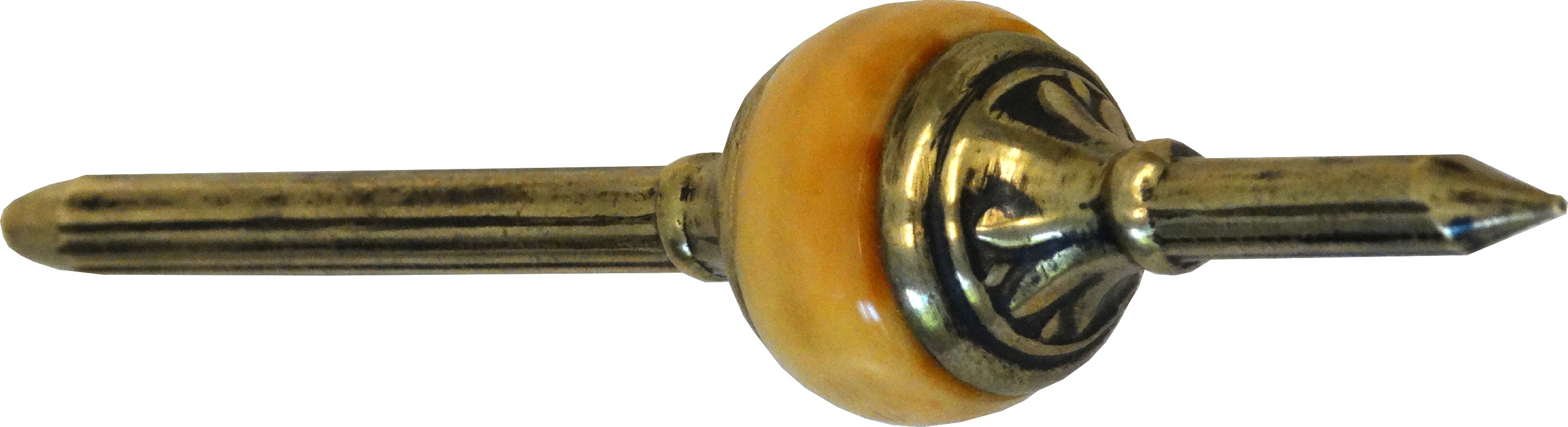
I shall give a more detailed description of the calculating machine another time, but now, and in haste, I shall write only this. aaa are the heads of the raised cylinders, on which the multiplications of the digits are inscribed, and they come forth, as much as they need, through the windows bbb. ddd have attached rolls with 10 teeth inside, put together in such way that, when the one on the right is moved ten times, the next left moves once, or that the right one moves 100 times, the third one moves once etc. And indeed in the same direction; which, in order to perform this, an intermediate gear like h was needed. Each middle one moves all the left ones, in due proportion; this is not true to the right, which required special attention. The numbers on them protrude through the ccc holes in the middle step. Finally, in the lower level, e are knobs and f likewise marks the holes for the appearance of the numbers, which can be used between operations. But this cannot be written in such a tumultuous manner, and can be more easily seen on examination. And I had already arranged for you to have a copy by our Johannes Pfister but this half-finished one together with some of my other things, specifically some copper plates, caught fire three days ago, in a fire that broke out unexpectedly at night, which Mästlin will be able to tell you more about. I bear the loss of these very grievously. Especially now, when he has no time to repair other things as quickly.
Kepler, J., Caspar, M., van Dyck, W. Gesammelte Werke. Briefe 1620-1630, München, 1959
The (re)discovered sketches and letters were interpreted in the 1960's by Baron von Freytag-Löringhoff, and since then we have a relatively good idea of how the machine worked. Many replicas have been built, some more authentic than others.
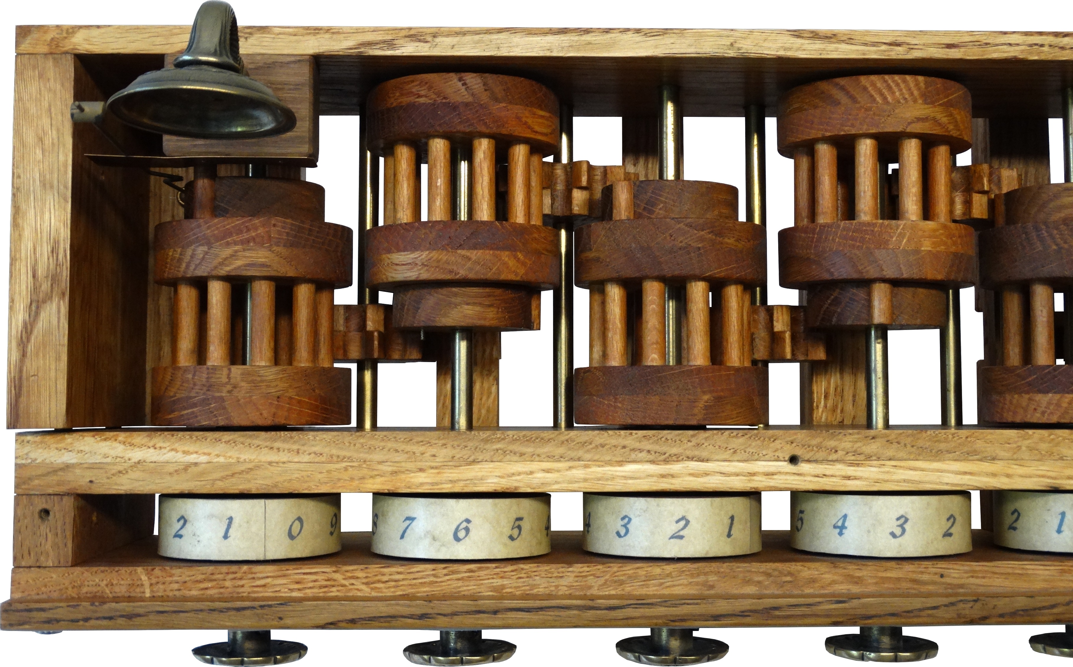
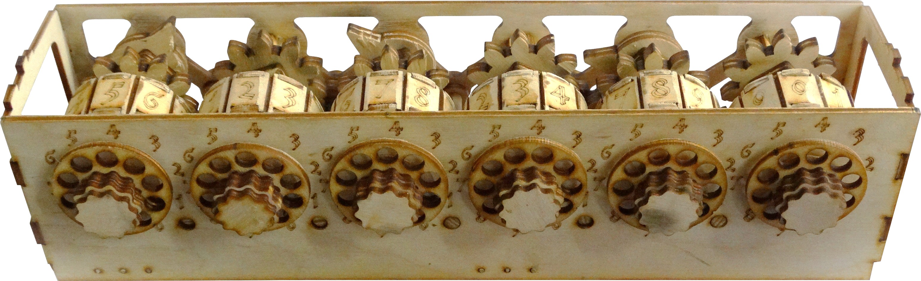
This replica of Schickard's calculating clock was built by Werner Starzl, a former office machine mechanic, using contemporary techniques and materials, based on the surviving sketches . It is an interpretation of what the finished machine would have looked like in 1623. An attempt was made to use as many stylistically correct elements and techniques as possible. The machine was built from a single oak tree.
What happened to Schickard's own example of the machine (the finished one that did not burn) is unclear. Schickard's entire family, the last being himself, died of the plague in 1634-1635. The second example of the machine built for Kepler was destroyed in a nocturnal fire in the workshop of Schickard's mechanic, Johann Pfister, in February 1624. The description given to Kepler, the instructions given to the mechanic who built the machine, and the surviving sketches make it possible to construct a working replica. Of course, there are still uncertainties, but at least this machine looks like the sketch and works admirably.
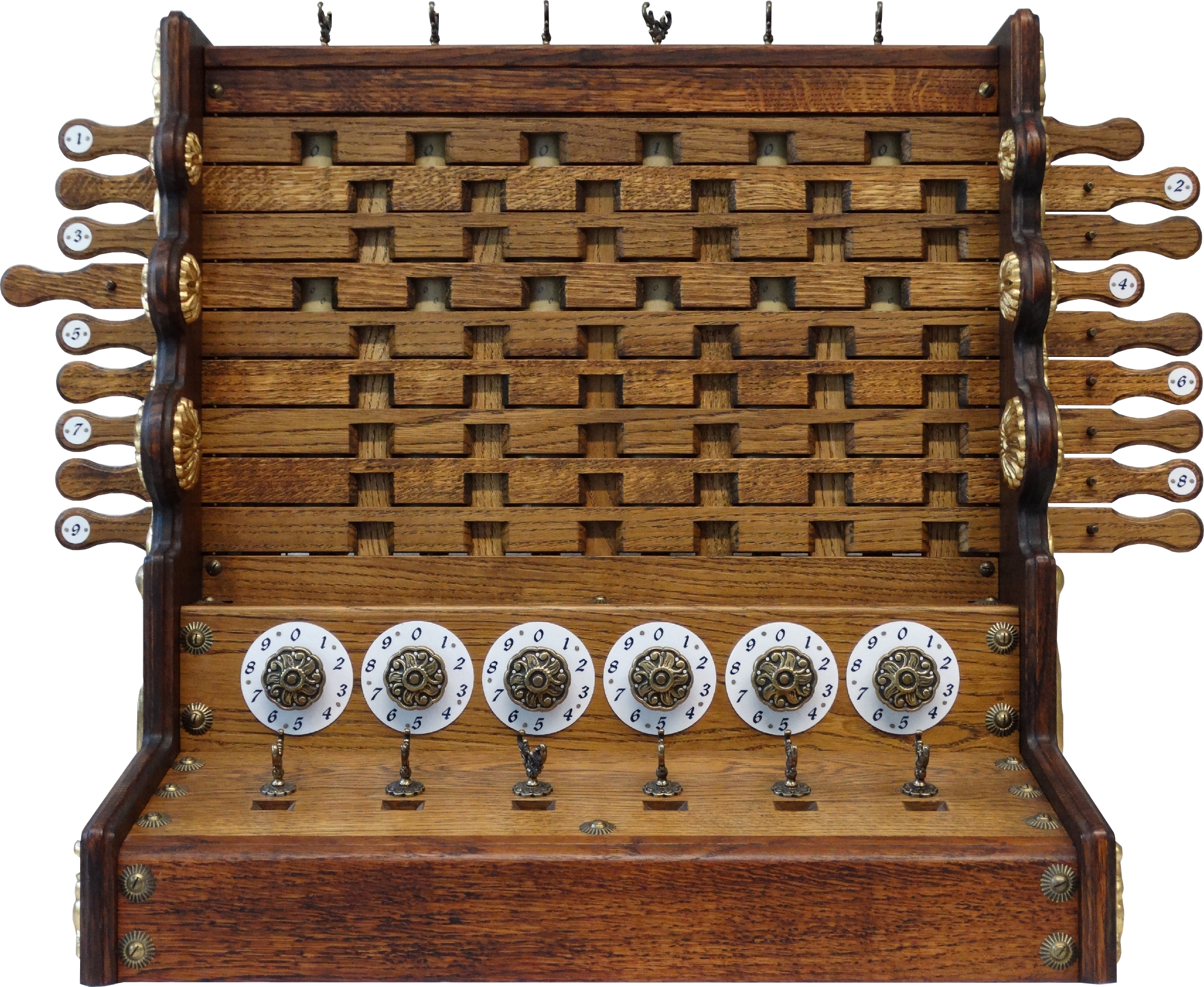
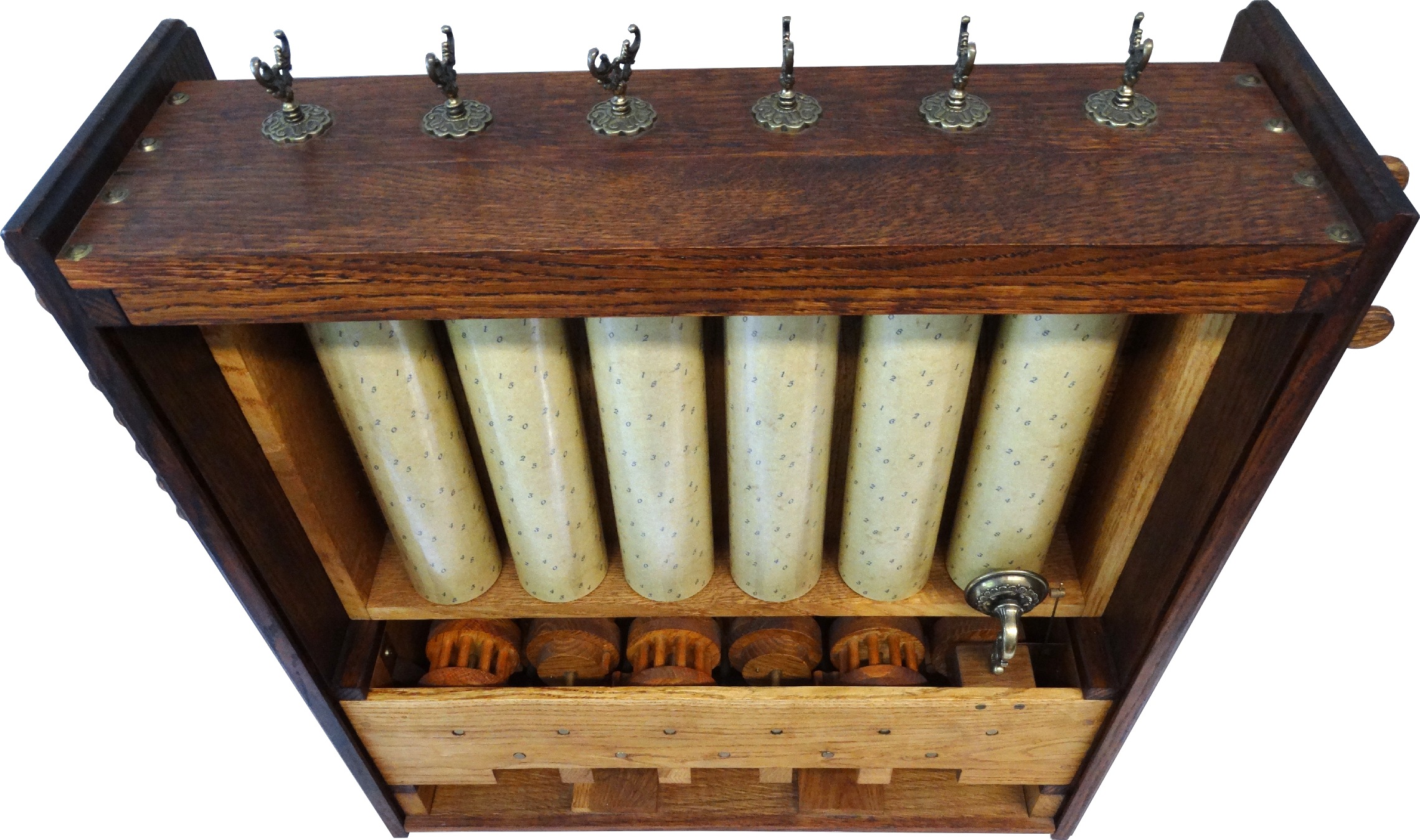
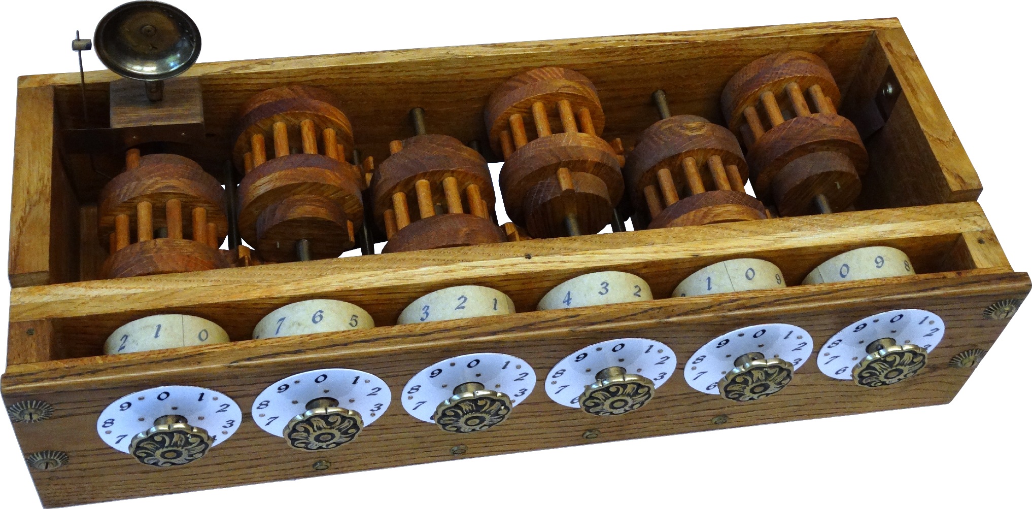
Collection: Werner Starzl
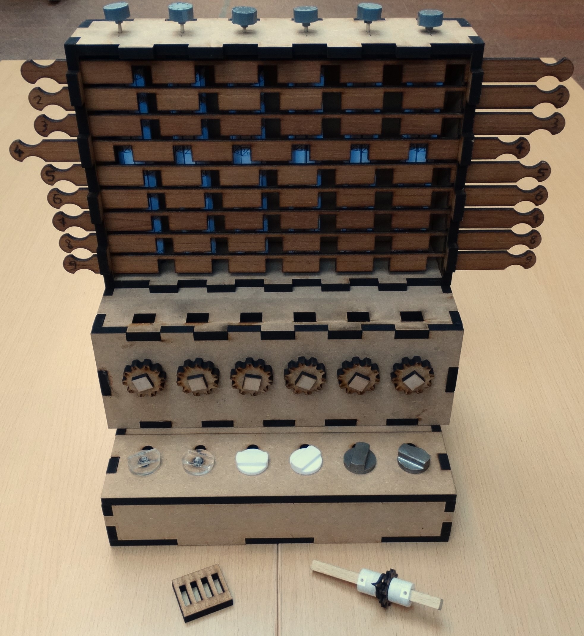
This laser-cut multiplex replica of the machine gives a better understanding of the presumed working mechanism of the machine - the gears with cut teeth are driven by a single tooth on the adjacent axle during the carry of tens. All axles are held in the correct position by springs. This model was drawn by Jürgen Weigert, and is freely available on the Thingiverse.
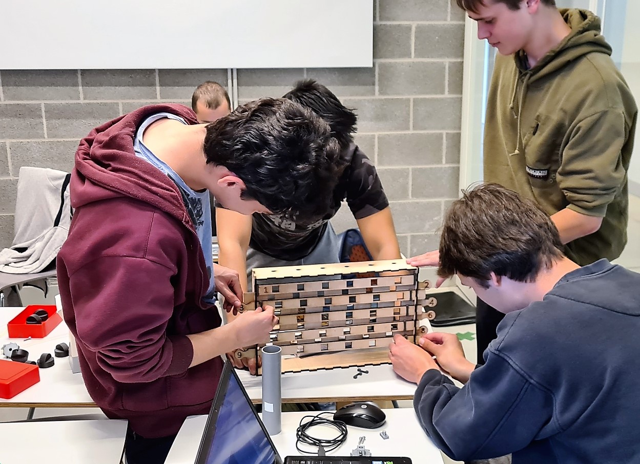
So what happens when you ask electromechanical engineering students to design a mechanical calculating clock?
Mechanical design is a very broad area that is part of a number of courses in the industrial electromechanical engineering curriculum. In the academic year 2022-2023, 3rd year bachelor students were given the task of working in small groups to design and build one of the three parts of Schickard's machine (the memory, the multiplier or the adding mechanism). The aim was not to build an exact copy, but to apply all parts of the course as much as possible.
After studying Schickard's original design, they had to come up with their own design, where the choice and motivation of the production method (3D printing, laser cutting, turning or milling, ...) was important. For most manufacturing processes, a CAD model had to be developed. The design had to take into account that the final product should be easy to integrate ("Design for Assembly"), easy to disassemble ("Design for Disassembly") and easy to maintain ("Design for Maintenance"). Other aspects of the group work included creativity, risk analysis (Failure Mode and Effects Analysis), costing, project planning and meeting techniques.
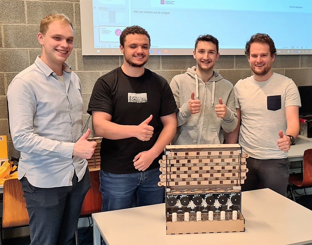
Once the parts had been manufactured (and some purchased), assembly and testing could begin. As the semester progressed, the status of the project was presented to the other groups, so that in the end the three parts could be assembled into a calculating clock. The three calculating clocks in the exhibition are certainly not the most perfect realisations, but they allowed the students to experience all aspects of design 'by doing'. The students' motivation and enthusiasm is a good example of how this applied approach adds value to the curriculum.
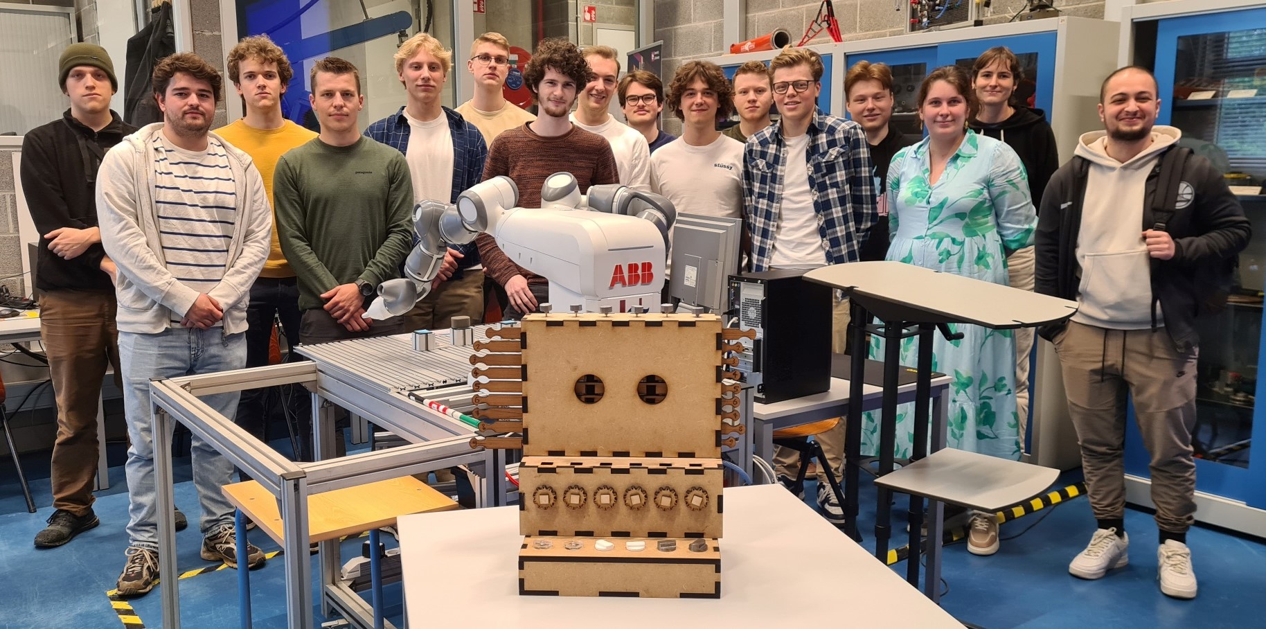
Students of group A1, B1 and C1 (Antwerp), May 2023
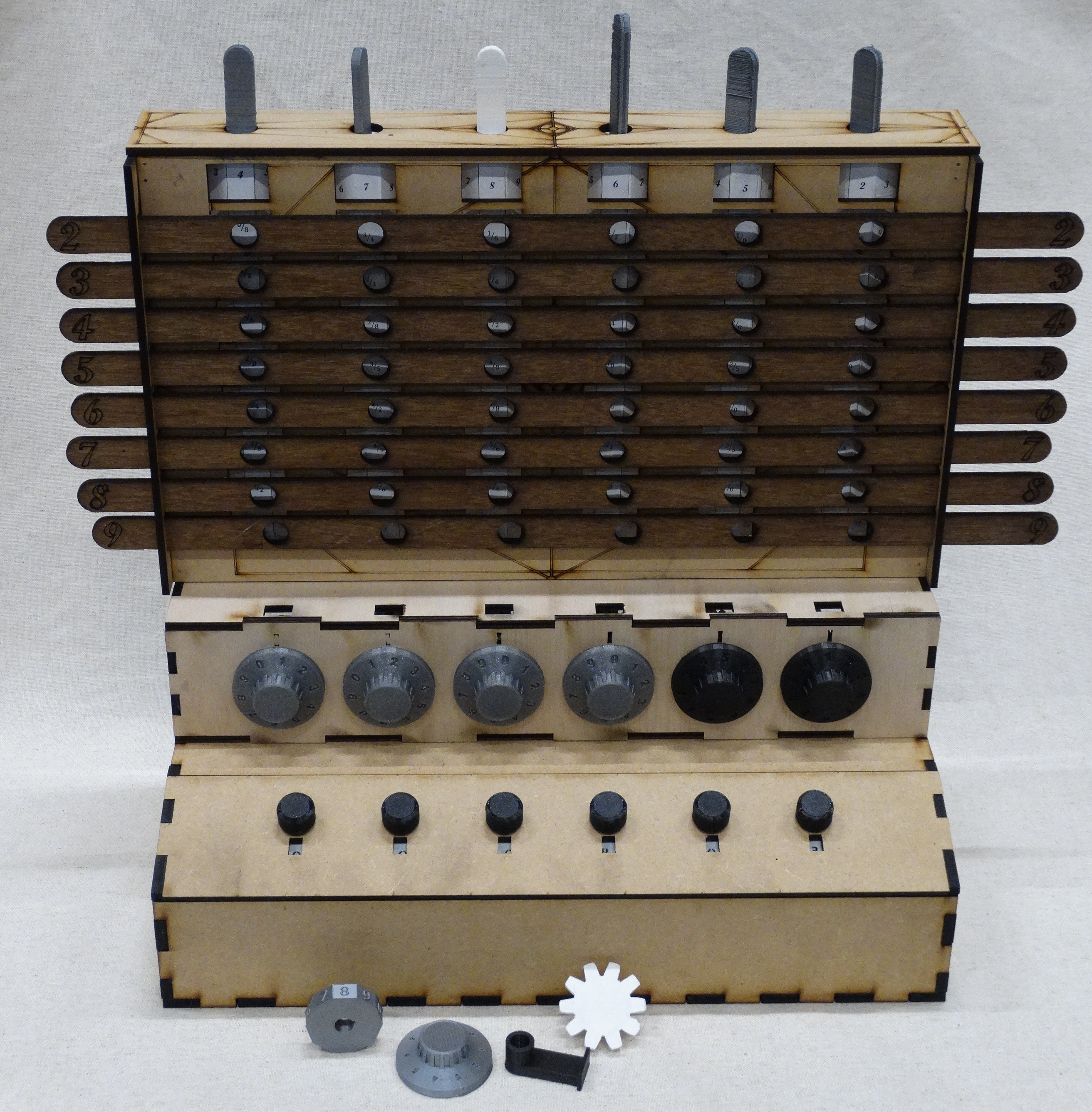
The three groups have mostly used MDF in their design, and the casing parts have been made by laser cutting. Different production techniques have been compared for the knobs in the memory.
Collection: University of Antwerp
Realised by: Sofiane Dahouch, Elien Decaesteker, Wout De Smit, Arnaud De Vooght, Dries Ian, Bryan Duffeleer, Aude Geeraerts, Dries Gentjens, Gilles Gootzen, William Pietermans, Laurens Schouwaerts, Toon Smets, Merlijn Stoffels, Iven Suykens, Wout Suykerbuyk en Nicolas Telen.
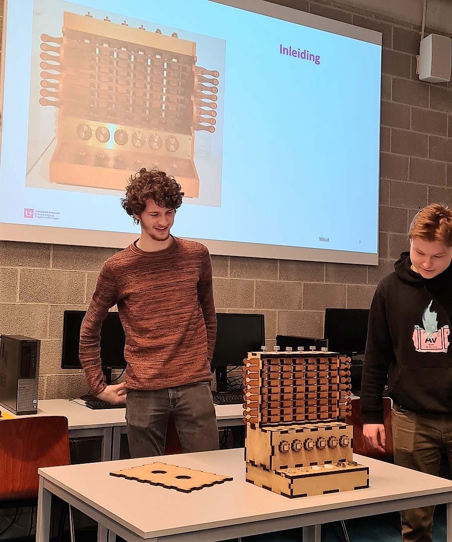
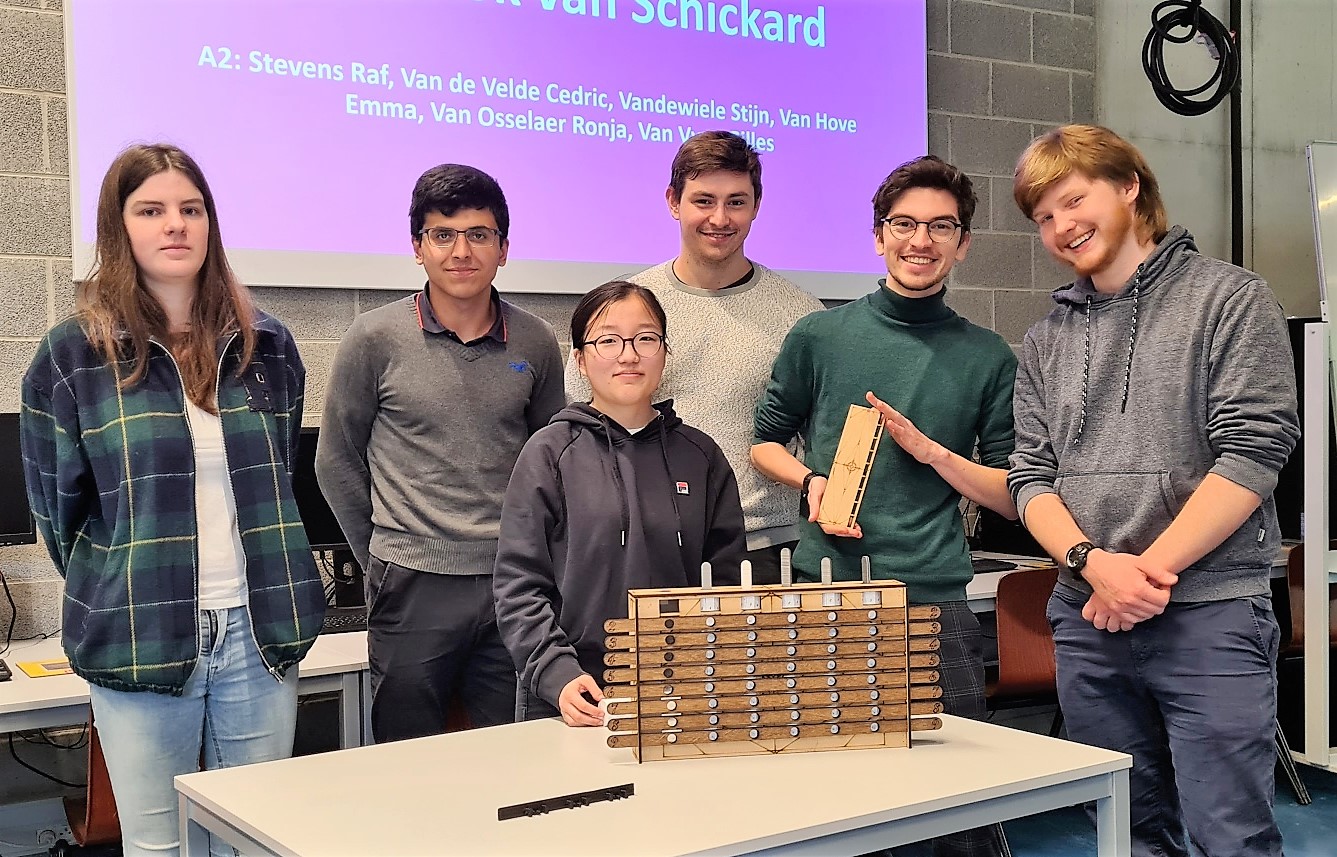
Students in groups A2, B2 and C2 (Antwerp), May 2023
In addition to MDF, acrylic was also used in the construction. Most of the visible parts are laser cut. A number of parts were made using a 3D printer.
Collection: University of Antwerp
Realised by: Cedric Van de Velde, Stijn Vandewiele, Emma Van Hove, Gilles Van Vyve, Raf Stevens, Ronja Van Osselaer, Ali Ahmindach, Kobe Anthonis, Mattis De Coninck, Shawn Decoster, Mattijs Devlieghere, Baptist Elst, Mats Hoebus, Vincent Jacobs, Bart Lagae, Hendrik Peeters, Norio Pétré en Fabian Serkeyn.
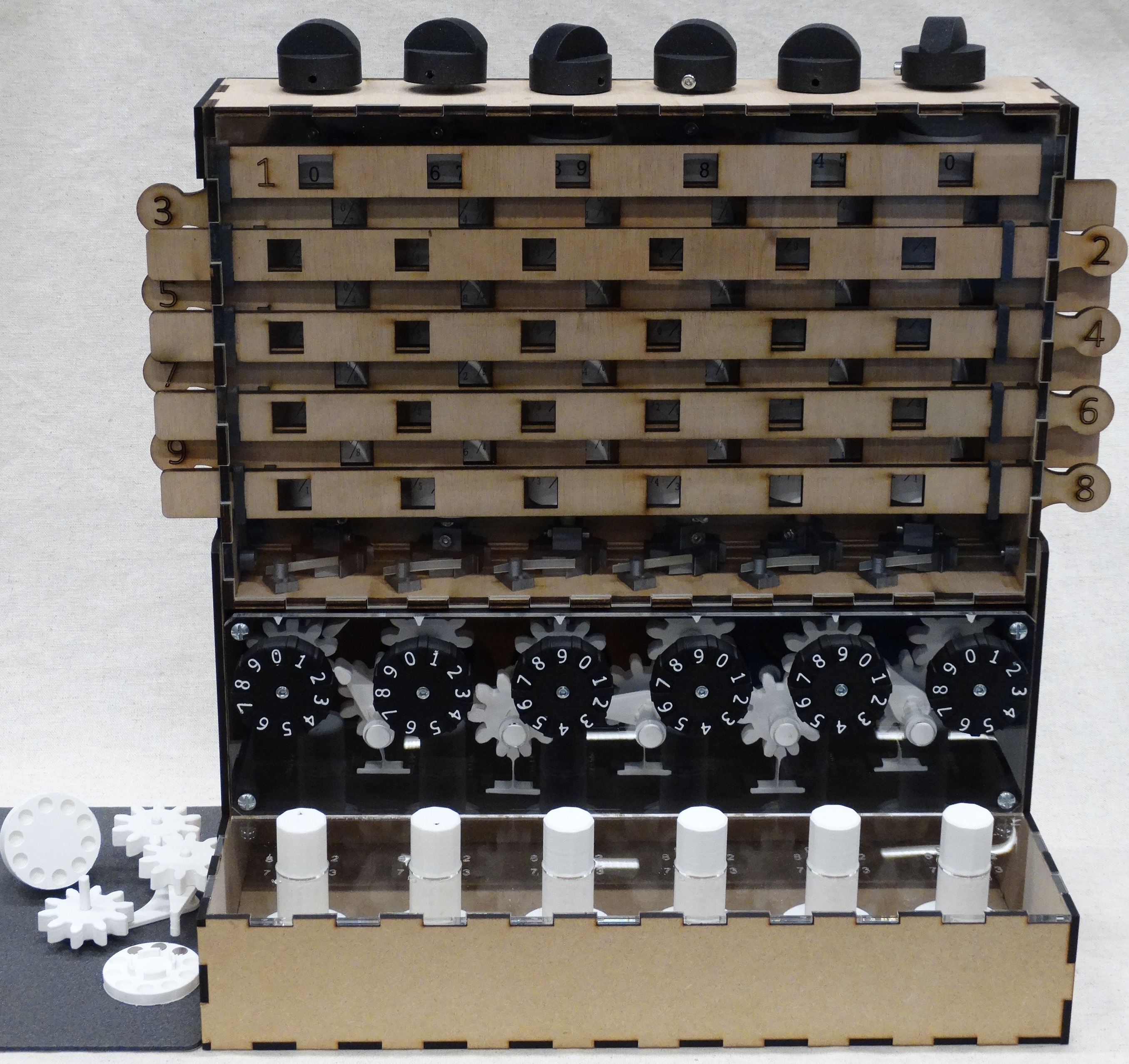
Students of groups A3, B3 and C3 (Antwerp), May 2023
The three groups have mainly used MDF, multiplex and acrylic (laser-cut), with a number of parts made using a 3D printer. Uncontrolled overshooting of the result wheels is prevented in an original way by using magnets instead of springs.
Collection: University of Antwerp
Realised by: Jasper Tack, Ferre Vanbaelen, Ken Van Laer, Vincent Vercammen, Wolf Vierbergen, James Xia, Mathijn Bogaert, Samir El Makrini, Arne Janssens, Ruben Janssens, Ben Kennes, Mohamed Mokhtari, Vincent Nuyttens en Lander Werrebroeck.